
Comparison map
Reflection and Plane Mirrors: relationships and examples
Connect a geometrically consistent ray diagram to a virtual image.Exam cue: A virtual image position cannot collect the reflected rays on a screen there.
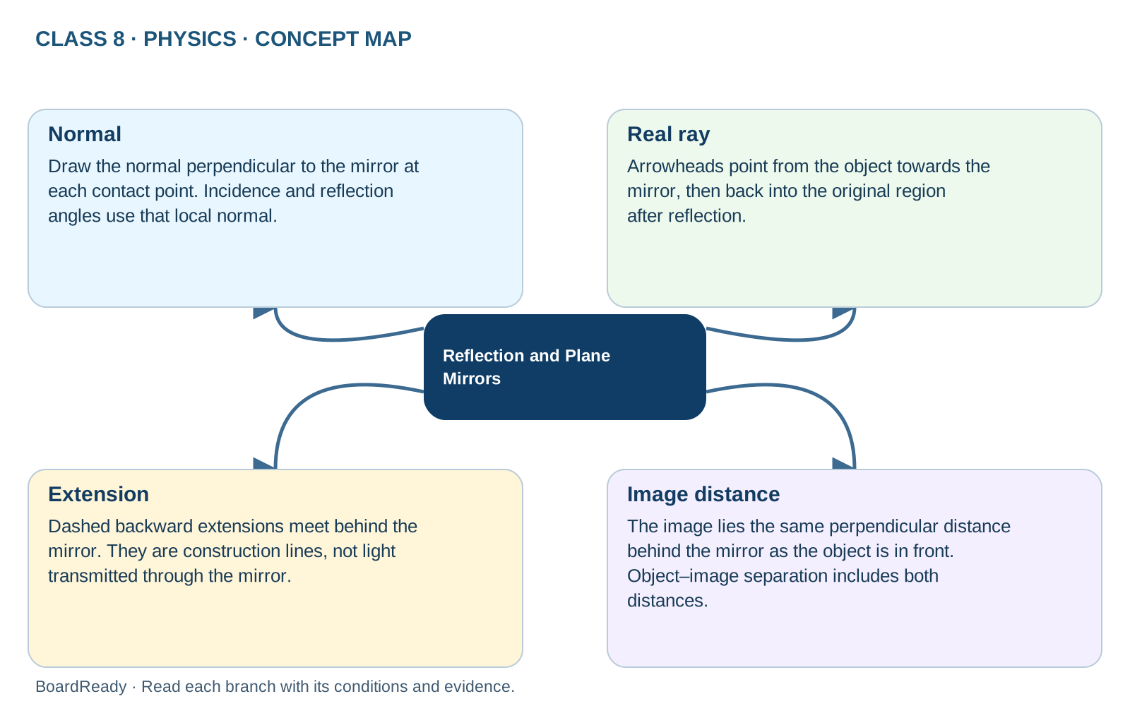
- 1Reflection and Plane Mirrors -> Normal: Draw the normal perpendicular to the mirror at each contact point. Incidence and reflection angles use that local normal.
- 2Reflection and Plane Mirrors -> Real ray: Arrowheads point from the object towards the mirror, then back into the original region after reflection.
- 3Reflection and Plane Mirrors -> Extension: Dashed backward extensions meet behind the mirror. They are construction lines, not light transmitted through the mirror.
- 4Reflection and Plane Mirrors -> Image distance: The image lies the same perpendicular distance behind the mirror as the object is in front. Object–image separation includes both distances.