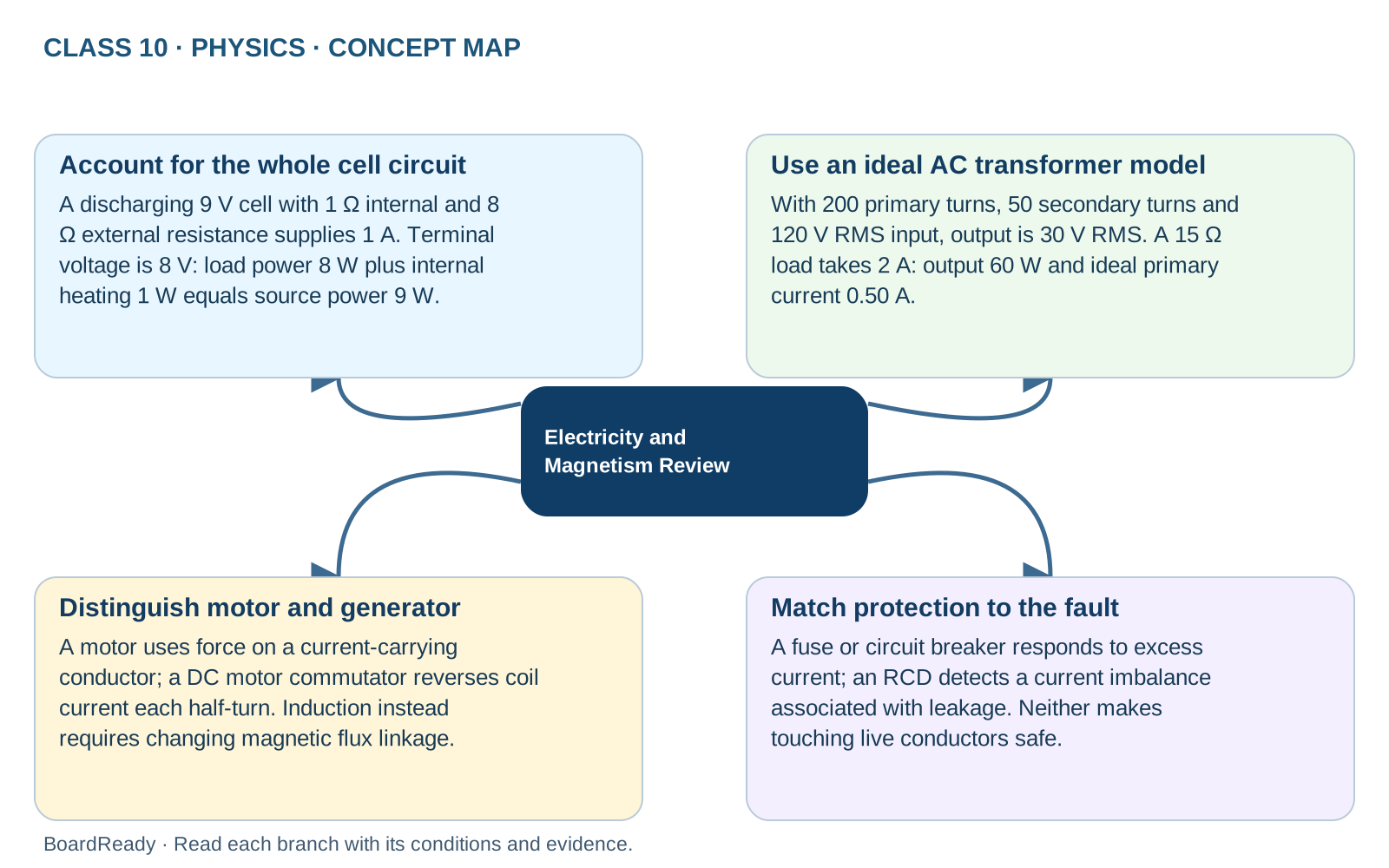
Electricity and Magnetism is revised best by linking these ideas: Electric Current and Potential Difference, Ohm's Law, Resistance and Resistivity, Resistors in Series and Parallel, EMF, Terminal Potential Difference, and Internal Resistance, Electric Power, Household Circuits and Electrical Safety, Magnetic Field and Field Lines, Force on a Current-Carrying Conductor, DC Motor, Electromagnetic Induction, Transformers, Domestic Electric Circuits. Keep each topic tied to its formula, diagram, observation, or physical rule.
Electricity and Magnetism Review: relationships and examples
Connect circuit energy, internal resistance, transformer ratios and changing magnetic flux. Identify the physical mechanism before choosing an equation.
Exam cue: Assume a steady discharging cell and an ideal transformer with AC input. A steady DC supply does not sustain transformer action. This is a circuit model, not wiring advice.
1Electricity and Magnetism Review -> Account for the whole cell circuit: A discharging 9 V cell with 1 Ω internal and 8 Ω external resistance supplies 1 A. Terminal voltage is 8 V: load power 8 W plus internal heating 1 W equals source power 9 W.
2Electricity and Magnetism Review -> Use an ideal AC transformer model: With 200 primary turns, 50 secondary turns and 120 V RMS input, output is 30 V RMS. A 15 Ω load takes 2 A: output 60 W and ideal primary current 0.50 A.
3Electricity and Magnetism Review -> Distinguish motor and generator: A motor uses force on a current-carrying conductor; a DC motor commutator reverses coil current each half-turn. Induction instead requires changing magnetic flux linkage.
4Electricity and Magnetism Review -> Match protection to the fault: A fuse or circuit breaker responds to excess current; an RCD detects a current imbalance associated with leakage. Neither makes touching live conductors safe.
Lesson
Step-by-step lesson
10 sections
Read the full lesson below, or jump to the section you need.
Concept01 / 10
Connect charge, energy and changing fields
Current measures charge flow per time and potential difference measures energy transfer per charge. A component can transfer energy while equal steady current enters and leaves it. Series and parallel rules follow circuit connections; a cell’s internal resistance makes discharge terminal voltage lower than emf. Magnetic forces act on current-carrying conductors with an orientation-dependent direction, whereas induction requires changing flux linkage. Motors use magnetic torque to transfer electrical energy to mechanical work; transformers use changing flux to relate AC voltages and currents.
Remember02 / 10
Name the circuit model before using a relation
R = ρL/A needs a specimen geometry and material conditions. Ohm’s law describes proportional V and I over a range under fixed physical conditions, not every heating filament. For a discharging cell, V = E − Ir and I = E/(R + r) belong to the stated external-load model. For an ideal transformer, rms voltage ratio follows turns ratio and ideal input power equals output power. Electrical power, energy and charge have different units. Household parallel-branch models and protective-device roles explain principles; they do not establish practical cable or fuse ratings.
Worked example03 / 10
Apply the physics
A₁₂V ideal supply feeds 6 Ω and 12 Ω resistors in parallel. Find total current, total power and energy transferred in 10 s.
Method
1Branch currents are 12/6 = 2 A and 12/12 = 1 A; total current is 3 A.
2P = VI = 12 × 3 = 36 W; E = Pt = 36 × 10.
Answer: Total current is 3 A, power is 36 W and energy transferred in 10 s is 360 J.
Misconception04 / 10
A distinction that matters
The 12 V supply divides into 6 V across each parallel resistor.
Correction: Parallel branches span the same two supply nodes, so each resistor has the full 12 V across it.
Exam tip05 / 10
Check the reasoning
A₁₂V discharging cell with internal resistance 1 Ω supplies an external 5 Ω load. Current is 2 A, terminal voltage is 10 V, useful load power is 20 W and internal heating power is 4 W. The source's 24 W account therefore balances. An ideal 10:1 step-down transformer receiving 200 V rms AC instead gives 20 V rms; it cannot be substituted directly into this steady DC-cell example and assumed to maintain transformer action. Distinguish charge flow, voltage, power and changing magnetic flux. A magnetic field's presence alone does not prove induction, and a switch or fuse model is not a practical wiring design.
Example06 / 10
Self-check with an explained answer
Question: A stationary magnet remains beside a stationary open coil with unchanging flux. Is a sustained emf guaranteed by the field’s presence? Answer: No. Changing flux linkage is needed for induction. A changing-flux open coil can have an emf without a continuous circulating current; being open and having no induced emf are different conditions.
Concept07 / 10
Trace directions and energy accounts separately
Around a straight wire, the right-hand grip rule uses conventional current to set field direction. A conductor in an external field has force magnitude BIL sin θ; reversing one of current or field reverses force, while reversing both preserves its direction. The motor’s split ring changes coil connections each half-turn, but a simple coil still has zero-torque orientations. An RCD responds to outgoing/returning current imbalance, whereas a fuse or overcurrent breaker responds to excessive current. No single diagram label replaces a full circuit or energy account.
Worked example08 / 10
Worked case: account for load and internal heating
A 9.0 V discharging cell with 1.0 Ω internal resistance supplies an 8.0 Ω external resistor. Find current, terminal voltage and the power transfers.
Method
1Current I = E/(R + r) = 9.0/(8.0 + 1.0) = 1.0 A.
2Terminal voltage = E − Ir = 8.0 V, equal to IR. Load power = I²R = 8.0 W; internal heating = I²r = 1.0 W.
3Source power EI = 9.0 W, equal to the 8.0 W external transfer plus 1.0 W internal transfer.
Answer: Current is 1.0 A and terminal voltage is 8.0 V. Including internal heating closes the power balance. EMF is 9.0 J/C, not a force of 9 N, and the discharge equation is not a universal equation for charging.
Worked example09 / 10
Worked case: combine turns, load and power
An ideal transformer has 200 primary turns and 50 secondary turns. The input is 120 V rms AC, and a 15 Ω resistive load is connected to the secondary.
Method
1Secondary voltage = 120 × 50/200 = 30 V rms.
2Secondary current = 30/15 = 2.0 A, so output power is 60 W for this resistive load.
3Ideal input power is also 60 W; primary current = 60/120 = 0.50 A.
Answer: The secondary delivers 30 V and 2.0 A; the ideal primary takes 0.50 A. Lower voltage goes with higher current in the ideal loaded account, not increased power. Losses would require more than 60 W input; steady DC does not maintain ordinary transformer operation.
Misconception10 / 10
A larger V/I is not evidence that charge is being consumed
Less current leaves a resistor because some of the entering charge has become thermal energy.
Correction: In a steady single-path circuit, equal current enters and leaves the resistor. The component transfers electrical energy to thermal stores while charge continues through the circuit; V/I at an operating point describes resistance.
Quick check: Have you separated energy per charge from the conserved flow of charge?
Current is the rate of flow of charge, and potential difference is the work done per unit charge.
An ammeter must be placed in series with a component to measure current, while a voltmeter should be connected in parallel to measure potential difference across that component. In exams, ensure you know the correct placement of meters and understand Ohm's law. A common mistake is forgetting to convert units correctly when using formulas.I=Q/t,V=W/Q.
Electric Current and Potential Difference should be revised by linking the physical idea, the formula or diagram cue, and the final result.
Keep the physical observation and the reason separate, then connect them clearly.
Recall the full chapter structure of Electricity and Magnetism.
Connect laws, diagrams, formulae, and observations across topics.
Practise
Check your understanding
Start with a short MCQ set, write an answer, or combine both in a lesson test.